| Previous | Main | Up | Next |
|
|
This exercise uses the code we just developed to blink an LED on a solderless breadboard.
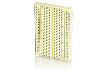
Take a look at your breadboard. Note that breadboards are designed so that all five holes in a row are connected. Also note that the five holes on one side of the middle gutter are NOT connected to the five holes on the other side. For the workshop we handed out breadboards with either 35 rows or 17 rows. So you have either a 350 hole or 170 hole breadboard. When you buy a breadboard you'll see this as "350 points" or "170 points". Breadboards are designed with holes 0.1 inch apart, or 2.54mm. This is the same pin distance used on most DIP chips. For example, you could insert your G2553 directly into the breadboard.
You can buy solderless breadboards from many places, like Radio Shack . These often come with two additional vertical columns of holes on each side. One column has a blue line next to it, the other a red line. Unlike the rows, these connect all the holes in a colum together. These are used to make it easier to provide power and ground anywhere on the breadboard. Without these you'll often have a lot of longer wires running across the project. For small breadboards like the ones in this workshop this isn't much of an issue.
|
To get started, unplug your LaunchPad board. It's a bad idea to plug and unplug wires or components into a board that has power. The spikes and surges from connecting wires can damage components, like the MSP430.
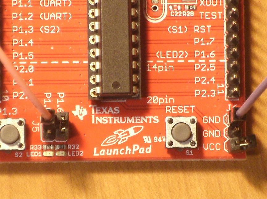
Remove the small black plastic jumper from the left pins in J5. To avoid losing it, or connecting the next wire to the wrong pin, place it over the VCC pin in J6. Connect one of your jumper wires to the upper pin in J5, not the lower pin. The upper pin is the one which is controlled by your MSP430 program. The lower pin just connects directly to the red LED, LED1, through the resistor, R33. Connect the other jumper wire to one of the two ground pins - it doesn't matter which one.
|
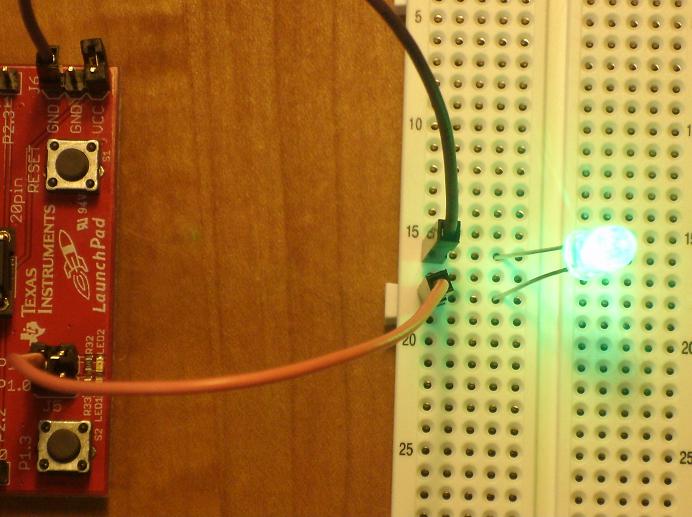
Now plug the other end of each wire into a different row on the breadboard. Remember the five points on each row are all interconnected. Insert the LED into the two rows you selected for your jumper wires. One pin of the LED is shorter and that side of the plastic housing is flat. This indicates the ground pin. LEDs only work one way, so if you plug it in backward it won't light up. The ground pin of your LED should be connected to the GND jumper wire. Plug your board back into the USB port of your computer. You should see a very bright flashing LED!!
|
You will seldom wire an LED like this. Almost always you'll use a resister in the circuit, just like Texas Instruments did. If you look at the LaunchPad board you'll see R33 and R32 between the jumper pins and the LEDs on the board. To keep our part list simple for this workshop we specifically picked an LED that can handle more voltage than the MSP430. While this reduced our cost and the number of parts we needed to hand out, the LED is dangerously bright. Don't look directly down at the LED as it will hurt your eyes. Of course you could use this as a simple night light project.
The datasheet for our LED is here. On page 2, the middle table indicates the maximum forward voltage is 4V, which is about half a volt more than the LaunchPad board provides. The lower table indicates the maximum reverse voltage is 5V, so even if you plug it in backwards you won't burn out the LED.
| Previous | Main | Up | Next |